


 Title Index
 Recently Changed
 Page Hierarchy
 Incomplete
 Tags
Tags


The networking stack that is exposed in Synergy ∞IPV is very powerful. Depending on the physical configuration of your Synergy ∞IPV box you can have access of up to 4 10/100/1000 ports. Each physical port is capable of bridging between the other ports in the system. Each port can run multiple IP address, DHCP servers , and VLAN. It is also possible to configure the Synergy ∞IPV box a full NAT router with support for firewall rule sets.
Note: While Synergy ∞IPV support multiple IP address and sub net's only one interface can be configured as a WAN interface.
Default IP Address/Network Information:
By default Synergy ∞IPV provisions a IP of 192.168.4.1 with a sub net mask of 255.255.255.0 on its second network interface. When uploading your first configuration to the system you will need to put your computer into the same sub net and upload it to 192.168.4.1 if your network does not have a DHCP server. This interface sub net will always be active even once you have configured your own network setting in to the system.
Ethernet Port Configuration:
General Settings:
Each physical port has a primary IP setting this is done in the general settings section.
| Setting | |
|---|---|
| IP Address | The ip address to use as the interfaces primary IP |
| Mask | The sub net mask for the primary IP |
| Broadcast | The broadcast IP for the primary IP. You can leave this value blank and the system will auto configure it. |
| Net | The network address of the primary IP. You can leave this value blank and the system will auto configure it. |
| Gateway | The gateway used to access the outside world. Only one gateway address should be set in the system all others should be blank. |
VLANS:
Each interface can support an unlimited number of VLAN interfaces. Just each physical interface can be part of the same VLANS depending on the applications needs. Just make sure to create a different IP address for each VLAN on each physical interface.
| Setting | |
|---|---|
| VLANID | The VLANID used by the VLAN is the same value set as your managed switches. |
| IP Address | This is the IP address that will be used by this port for traffic on this VLAN to and from this interface |
| Mask | The is the sub net mask for the VLAN |
| Start IP | The first IP to hand out to clients when requesting an IP via DHCP on the VLAN ID. Leaving this value blank will disable the DHCP server from handing out an IP address to clients on this VLAN. |
| End IP | The last IP to hand out to clients when requestingan IP via DHCP on the VLAN ID. Leaving this value blank will disable the DHCP server from handing out IP address to clients on this VLA |
Note: It is currently not possible to assign a gateway address to a VLAN interface. This means that it will not be possible to provide WAN access to the Synergy ∞IPV box over a TAGED VLAN port it must be untagged.
IP Alias:
Each physical port can have multiple IP alias these are non-VLAN IP's. If you run multiple sub nets and don't use VLANS then you can build alias so they can communicate with Synergy ∞IPV.
| Setting | |
|---|---|
| IP Address | The alias IP to use |
| Mask | The sub net mask to use with the alias IP |
DHCP Service:
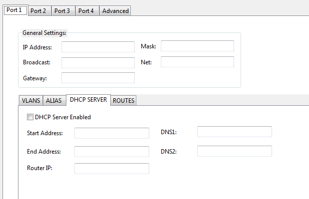
If you wish to run a DHCP service from the primary IP address assigned in the General settings section of the port configuration, this section will allow you to configure the first and last IP address the DHCP server will deliver to clients. A DHCP service running off the primary IP address will NOT interfere with DHCP services running of the VLAN interfaces on the same port. An example of how this functionality can be used it configuring the primary IP DHCP server to hand out IP to end user computers. Configure your IP phone to work on a VLAN. Then setup a matching VLAN interface with a DHCP server and the phones will get IP's in the VLAN range.
| Setting | |
|---|---|
| Start Address | The first IP address to hand out to devices requesting an IP |
| End Address | The last IP address to hand out to devices requesting an IP |
| Router IP | The rotuer/gateway IP to hand out to devices requesting an IP. If left blank will hand out the interfaces primiry IP and the Router IP |
| DNS1 | The primary domain name server to hand out. If left blank will hand out 208.67.222.222 (OpenDNS) |
| DNS2 | The secondary domain name server to hand out. If left blank will hand out 208.67.220.220 (OpenDNS) |
Routes:
You can enter multiple routes per-Ethernet port, the gateway address must be reachable by a IP Addressed assigned to the port the route is configured on. The IP address can be the ports primary IP, a VLAN or ALIAS IP address.
| Setting | |
|---|---|
| Network | The routable network you wish to reach. |
| Subnet Mask | The subnet mask for the network. |
| Gateway | The gateway address which can reach the network. |
Advanced:
The advanced section allows you to configure NAT and DNS settings and static IP assignment for all DHCP services on the system.
| Setting | |
|---|---|
| DNS Server 1 | The primary domain name server to hand out. If left blank will hand out 208.67.222.222 (OpenDNS) |
| DNS Server 2 | The secondary domain name server to hand out. If left blank will hand out 208.67.220.220 (OpenDNS) |
| NAT As Address | This is the WAN IP address to use for all traffic leaving the LAN going to the WAN. |
| Non NATed Sub Nets | These are sub nets which should never be NATed. Example input 192.168.0.1/255.255.255.0 |
Static IP Assignment via DHCP:
The DHCP server allows you to statically assign an IP address based on the mac-address of the device requesting an IP. The static IP assignment system allows you to assign a IP as well as a router for environments with multiple internet gateways. Along with Primary and Secondary DNS (domain name server). The manager application has a button called “Load All Aastra Endpoints” this will load all the Aastra endpoints with mac-address into the static DHCP table. It will pre-configure all information based on the settings found in port 2 DHCP configuration.
| Setting | |
|---|---|
| Label | A unique name used to label the static entry |
| MAC | The mac-address of the device |
| IP | The IP address to assign the device |
| Router | The gateway to assign the device. |
| DNS 1 | The primary domain name server to hand out. If left blank will hand out the IP configured in DNS Server 1 of the Advanced section. |
| DNS 2 | The secondary domain name server to hand out. If left blank will hand out the IP configured in DNS Server 2 of the Advanced section. |
You can hit the "Load ALL Aastra Endpoint" button and all extensions which have macadress set will popuplate the static IP table. If the macaddress is already in the table it will be skiped.
Port Forwarding:
When Synergy ∞IPV is acting as a router it is possible to setup portforwarding for services running inside the LAN.
| Setting | |
|---|---|
| TCP/UDP | Is the inbound traffice TCP or UDP |
| SRC | Optional source of the inbound connection |
| SRC Port | Optional source port of the inbound connection |
| DST | Optional destination of the inbound connection |
| DST Port | Destination port of the inbound connection. This is a required setting |
| Send To | The IP address to forward the connection to |
| Send To Port | The port to send the inbound connection to |
VPN Support:
Synergy ∞IPV supports Internet Protocol Security (IPSec) to create secure encrypted VPN tunnels over a public internet connection. IPSec sufficiently address the usability needs of organizations with branch offices or remote users. IPSec can be implimented two different was Host-to-Host WAN IP to WAN IP, or Network-to-Network (oneLAN/WAN to another). Synergy ∞IPV uses a pre-shared key which is known by both endpoints prior to establishing the connection.
Host-to-Host IPSec Tunnel:
In this tunnel configuration traffice between two public IP's is encrypted in a IPSec tunnel.
| Setting: | |
|---|---|
| Destination | The IP address of the remote system to create the IPSec tunnel with. |
| Pre-Shared Key | The pre-shared key used in phase one of the IPSec tunnel creation. |
Network-to-Network IPSec Tunnel:
This allows you to create an IPSec tunnel between two remote LAN segments.
| Setting | |
|---|---|
| Src LAN IP | The local LAN IP address on the Synergy ∞IPV system. |
| Src LAN Network | The network of the local LAN IP. |
| Dst LAN IP | The remote LAN IP address on the remote Synergy ∞IPV system. |
| Dst LAN Network | The network of the remote LAN IP. |
| Destination WAN IP | The remote WAN IP address of the Synergy ∞IPV system |
| Pre-Shared Key | The pre-shared key used in phase one of the IPSec tunnel creation. |